Software
E-TRAN
Users of electromagnetic transients (EMT) simulation programs (such as PSCAD/EMtdC) often face difficulties in obtaining data and developing cases suitable for their studies. Many utilities have the data available for their entire system in loadflow programs, but a great deal of effort is required to re-enter the network data for use in EMT programs.
There are three common challenges:
- Translation of circuit/network data (differences in PU systems, data entry, etc.)
- The generation of network equivalents
- Initialization of machines, generators or sources in large inter-connected networks
The Electranix Corporation was founded by experienced power system engineers Dennis Woodford and Garth Irwin who now offer consulting services specializing in loadflow, stability and EMT studies.
They developed the E-TRAN translator to automate the processes that were repeated for each new study performed for their customers. E-TRAN not only saves considerable time and effort, but it bestows confidence in the study results.
Features
Direct translation of Power System Data into PSCAD
Directly translates PSS/E loadflow files (.raw, .dyr, and .seq) into PSCAD .psc and .pscx files
Auto-Routing and Graphical Representation
E-TRAN will directly create PSCAD .psc files, complete with correct data for all busses, loads, DC links, switched shunt devices, br/anches, generators, transformers, phase shifters (etc..) all correctly drawn and graphically interconnected. E-TRAN translates an entire circuit, a zone or area, or a central bus and “N busses away”. Drawings are grouped by location and voltage level, and can be created for a complete network or a portion of a network.
Formation of Network Equivalents
The user identifies a portion of the network for a direct translation into PSCAD models (ie the “kept” network), and E-TRAN creates a network equivalent of the rest of the network based on the available fundamental frequency impedance and powerflow information. The equivalent is a multi-port representation that will be correct for steady state as well as for open circuit and short circuit conditions and contains Thevenin voltage sources to match PQ flow and represent generation in the equivalent network. The equivalents are generated based on the +ve sequence data entered in PSS/E .raw files, and includes the effect of -ve and 0 sequence data (if .seq files are available).
Initialization of Machines, Generators and Sources
The bus voltages and angles and PQ loadflow information (from the solved load flow input file) are used to directly initialize sources/generators in PSCAD (and to initialize non-linear loads etc.). The initialization information can be used in simple voltage source representations of generators, or can be used to initialize detailed machines, governors, exciters, multi-mass systems etc.. The resulting simulation in PSCAD will exactly match the solved load flow results for any circuit and complex systems with any number of machines can be initialized without startup oscillations.
E-TRAN Runtime Library for PSCAD
E-TRAN includes a downloadable Runtime Library for use in PSCAD. The E-TRAN library contains all models used in loadflow programs including load models, sources, transmission lines, transformers, phase shifters etc. It has data entry based on the same per-unit system and data entry standards as used in loadflow programs. PSCAD cases generated with E-TRAN can be freely distributed to other users without license fees. It also supports a substitution library, which allows a user to maintain and automatically substitute their own more-detailed models instead of simple RXB data.
Sanity Check and Data Verification
E-TRAN generates warnings and error messages when it reads in PSS/E .raw input files. This will inform the user of areas of mis-matched voltage levels, inconsistencies in the entry of data. The result messages are output to the E-TRAN log file.
Compatible with PSCAD V4.6 and V5
Theory
Auto-routing
The algorithm used to automatically generate the circuit layout in PSCAD based purely on busses and connection information (from the PSS/E.raw file) is based on Graph Theory.
Matching the Loadflow in PSCAD
The E-TRAN library for PSCAD contains models which mirror the functionality of the device models contained in PSS/E (constant PQ loads, for example). The E-TRAN program translates the results into PSCAD, and then the PSCAD differential equation solver is used during the run. The resulting solution will match the PSS/E loadflow results to about 3 or 4 decimal points everywhere in the system.
Initialization of Generators/Machines
The best method to initialize a large system in PSCAD is to set the initial voltage magnitude, phase angle, and PQ flow into machine/generator models, and then start each machine as a fixed frequency source. After a few cycles, the ac system in the simulation will reach the correct loadflow, at which point the machine’s electrical and mechanical systems can be initialized for a “bumpless” start. The transfer of all necessary initial condition information into PSCAD is automated by E-TRAN.
Network Equivalents
E-TRAN generates a complex admittance (Y) for the entire system (this can be > 50,000 busses). It then calculates the PQ mismatch of the entire system to see if the input .raw file is solved, and, decomposes using LDU sparse decomposition techniques to generate network equivalents.
Download Chapter 9 from the E-TRAN User’s Manual (E-TRAN_Chap9_Theory.pdf) for more information.
Examples
Example 1:
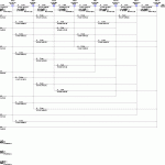
The first image shows a portion of a network near a bipolar HVDC converter station The circuit is loaded in PSCAD V4 and was directly generated by E-TRAN from a PSS/E .raw input file. (Click on the image to download a higher resolution picture.)
The original circuit was more than 18,000 busses, but, for this example, E-TRAN directly translated only 1 bus away (which resulted in a 15 bus circuit) from the HVDC bus and formed a network equivalent of the remaining circuit.
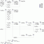
The second image shows the equivalent network on a sub-page. The voltage magnitude and phase angle of the equivalent sources are automatically calculated to match the power flow of the solved loadflow. Note the multi-port equivalent is valid for steady state as well as for open/short circuit conditions.
E-TRAN converted the circuit, using only the PSS/E .raw file, directly into a PSCAD Version 4 .psc file in three phase Single Line Diagram (SLD) format.
Example 2:
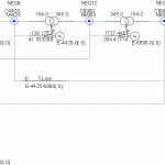
The first image shows a portion of a small network at a 345 kV bus. The circuit is loaded in PSCAD V4 and was directly generated by E-TRAN from a PSS/E .raw input file.
E-TRAN directly translated only 2 busses away from the main bus (which resulted in a 15 bus circuit) and formed a network equivalent of the remaining circuit.
The second image shows the equivalent network on a sub-page. Note that the interface busses are at different voltage levels and a transformer is automatically used for the off-diagonal branches instead of a pi section transmission line.
E-TRAN creates a log file which contains details of the conversion process and numerical output of the system admittance matrices. The log file for this small system is in the file “Example2.txt”.
In this case the entire circuit was only 160 busses, so it could have easily been translated and run in PSCAD without the need for any network equivalent.


